
Brake Testing Lab Workflow: Dyno, Track and Report in One Chain
Author

Neerav Singh
Technical Product Specialist
Author
Neerav Singh
Technical Product Specialist
Reading Time
3 min read
Brake Testing Lab Workflow: Dyno, Track and Report in One Chain
A good brake stops a 2 tonne car from 100 km/h in about 3 seconds. Moving that same brake from a dyno cell to the proving ground and into a signed report takes weeks.
Nobody loses those weeks on the dynamometer. Inertia dynos run around the clock and track engineers know their stopping distances to the metre. The weeks disappear between the stations, where one team hands a pad set, a rotor and a stack of results to the next.
Relay coaches spend more practice time on the baton change than on the sprint, because that is where races fall apart. Brake testing works the same way. This article runs one brake programme as a 3 leg relay and stops at each changeover zone to see what gets dropped.
Leg 1: the brake dyno
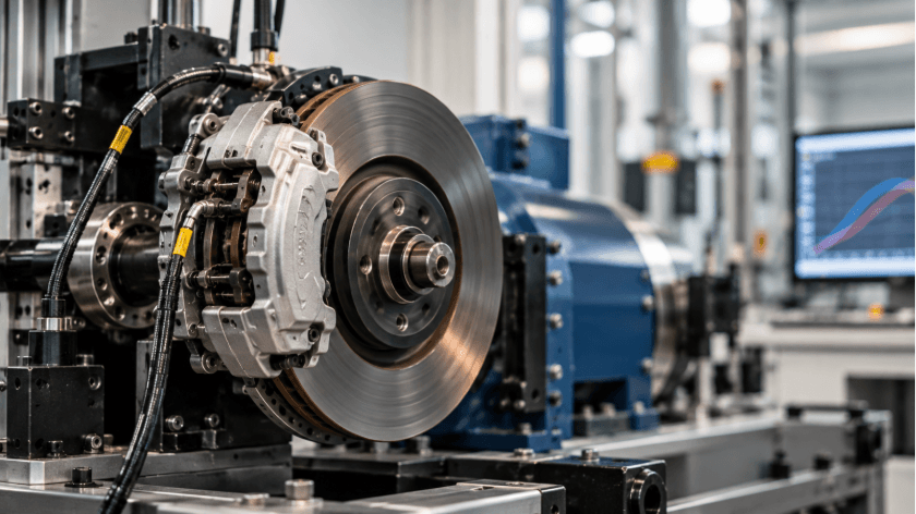
Every brake programme starts with an inertia dynamometer. The brake dyno simulates vehicle mass with flywheels or electric inertia, so engineers can run hundreds of stops under controlled pressure, speed and temperature without a prototype car.
A typical dyno leg for a passenger car brake covers 3 procedures:
- SAE J2522, better known as the AK Master, maps friction coefficient across green, bedded, speed and pressure sensitivity, fade and recovery sections
- SAE J2521 runs the squeal noise matrix for brake NVH
- SAE J2784 replicates the FMVSS 135 vehicle test sequence on the dyno so engineers can predict the track result before booking a car
Each run produces friction curves, rotor and pad temperatures, pressure traces and wear measurements. A clean AK Master result is the first baton.
Those 3 procedures rarely share a cell. Performance dynos and NVH dynos with acoustic enclosures are usually separate machines, sometimes in separate buildings. A single pad lot gets split across them, and the split needs its own record: which sets went to J2522, which went to J2521 and which were held back for the track. Lose that allocation and a pad set that squealed on the noise dyno can end up fitted to the prototype car.
The dyno has its own failure mode, and it rarely involves the dyno. A global OEM running multi cell powertrain testing lived with it for years: a test cell down for one missing part. Brake labs know the feeling well. The cell is free, the operator is ready and the caliper adapter or the correct rotor batch is still in a box at goods inwards.
That lab fixed it by modelling each cell as configurable equipment with its fixtures, adapters and capabilities attached. A booking only confirms when the parts it depends on are actually in inventory. For a brake dyno, that means the pad lot, rotor, caliper and adapter plate are all checked in before the slot locks. Every hour a cell sits idle waiting for a fixture adds to the real cost of an idle test rig, and brake dynos are expensive rigs to leave cold.
Where do you see the biggest delays in your brake testing workflow?
Vote and see how your peers voted!
Changeover zone 1: dyno to track
The dyno engineer has a passing AK Master. The track engineer needs to fit the same brake to a prototype and run FMVSS 135 or ECE R13-H at the proving ground.
Here is what the baton has to carry:
- Pad formulation and lot number
- Rotor part number and the exact rotor paired with those pads on the dyno
- Burnish state, because a dyno bedded pad and a fresh pad behave differently on the first stops
- Dyno friction summary with expected fade onset temperature
- Thermocouple positions used on the dyno so the track can mirror them
- Any deviations from the dyno procedure
In most labs that baton is an email with a PDF attached. The pad lot is in the PDF. The rotor pairing is in the technician's notebook. Nobody wrote down that the dyno run used an alternate caliper because the production part was late.
Then the track result comes in 8% off the dyno prediction and two teams spend a week arguing about correlation when the real cause was a hardware swap at the handoff.
A test article record that travels with the parts closes this zone. The pad set, rotor and caliper carry their identities, their dyno history and their burnish state from one station to the next. The track engineer opens the same record the dyno engineer closed.
Leg 2: the track
FMVSS 135 is the US standard for light vehicle brake systems. The vehicle goes through a burnish of 200 stops from 80 km/h, then cold effectiveness, high speed, fade and recovery, partial failure and parking brake tests. The cold effectiveness stop from 100 km/h has to come in within 70 m. ECE R13-H covers the same ground for UN markets. Aftermarket pad makers face ECE R90, which compares replacement pads against the original equipment.
Track time at a proving ground is booked in blocks and shared with ride and handling, ADAS, durability and NVH programmes. Weather cancels slots. Prototypes break. A brake programme that slips a day can lose a week waiting for the next open block on the braking surface.
Proving grounds carry their own version of the relay problem. Before moving to TITAN, an independent proving ground ran on bookings that did not talk to billing, PO limits missed until after the fact and asset tracking on paper. A brake programme that overruns its track block lands squarely in that gap. The customer finds out about the overrun when the invoice arrives. Connecting track bookings to billing and assets in one live system lets the programme manager see the PO burn while the car is still on the surface.
Changeover zone 2: track to report
The track engineer now holds stopping distances, pedal forces, deceleration traces, brake temperatures, ambient conditions, vehicle test mass and tyre details. The report author needs all of it alongside the dyno data from Leg 1.
This zone fails quietly. Track data sits on a logger laptop. Dyno data sits on the dyno PC. The report author copies values into a template by hand and a transcription error turns a 68 m stop into 63 m. Nobody catches it until a reviewer cross checks the raw file, if anyone does.
Brake reports for homologation or a customer sign off also need the procedure revision used at each station. A track run against one revision of the internal test method and a dyno run against another cannot be presented as one programme without a deviation note. Holding every brake procedure as a controlled entry in a test catalog means each test record points at the exact revision it ran.
Leg 3: the report
A brake test report that survives review ties the chain together in one place. It shows the dyno friction map, the predicted track performance, the measured track result and the gap between them, all linked to the same test articles.
Reviewers tend to check 4 things first: that the test articles match across stations, that every instrument was in calibration on the day, that track ambient conditions fell inside the procedure limits and that each deviation carries a sign off. A report that answers those 4 on its first page saves a full review cycle.
Automated test report generation pulls values straight from the dyno and track records into the report template, which removes the hand copy step where most transcription errors start. The multi cell OEM lab now runs this way, with one platform carrying every test from plan to report.
A fourth leg arrives in November
Euro 7 adds a new runner to the relay. From 29 November 2026, newly type approved passenger cars in the EU must meet a brake particle emission limit of 7 mg/km, or 3 mg/km for pure electric cars. The test runs under UN GTR 24 on an enclosed brake dyno driven through the WLTP brake cycle, measuring both particle mass and particle number.
That puts a brake emissions dyno leg alongside the performance dyno, the noise dyno and the track. Same pads, same rotors, one more changeover zone. Labs that already struggle to hand off between 2 stations will find 4 stations much harder.
Hold the baton
A brake programme is only as fast as its slowest handoff. The dyno can be world class and the track can be booked months ahead, and the programme will still stall if the pad lot, the rotor pairing or the procedure revision gets lost between them.
Labs that finish on time treat every changeover as a test step in its own right, with a record the next team can open and trust. On a connected chassis testing platform, the baton never leaves the system, so it never hits the ground
Connect Your Brake Testing Workflow
Subheading: Link dyno, track and reporting to reduce delays and keep every test asset in sync.
Recent Blogs
NVH Test Campaign Management from Component Rig to Full Vehicle
The decibel meter disagrees, of course. An electric vehicle is quieter overall than the combustion car it replaces.
Read more...

Beyond Go-Live: How Labs Mature on TITAN
A 2020 Boston Consulting Group study found that 70% of digital transformations miss their objectives, leaving just 30% that deliver
Read more...
THOR-50M vs Hybrid III: A Reference Comparison
Put a THOR-50M and a Hybrid III 50M through the same frontal crash test and they will tell you different stories about
Read more...
Test Lab Turnaround Time: How to Measure It and How to Cut It
Search for "lab turnaround time" and page 1 belongs to hospitals. The top results discuss specimen accessioning,
Read more...
Developmental Test and Evaluation: The Discipline That Decides Whether a Program Is Actually Ready
A brake controller program carries 312 verification line items across 4 development builds. Build 3 closes 287 of them.
Read more...

What Flight Test Management Covers
A certification campaign on a business jet clears 240 test points across 38 sorties. On sortie 22 the instrumentation
Read more...
The Real Cost of an Idle Test Rig
A 4-post hydraulic durability rig carries a replacement value north of $2 million. An environmental chamber rated for combined
Read more...
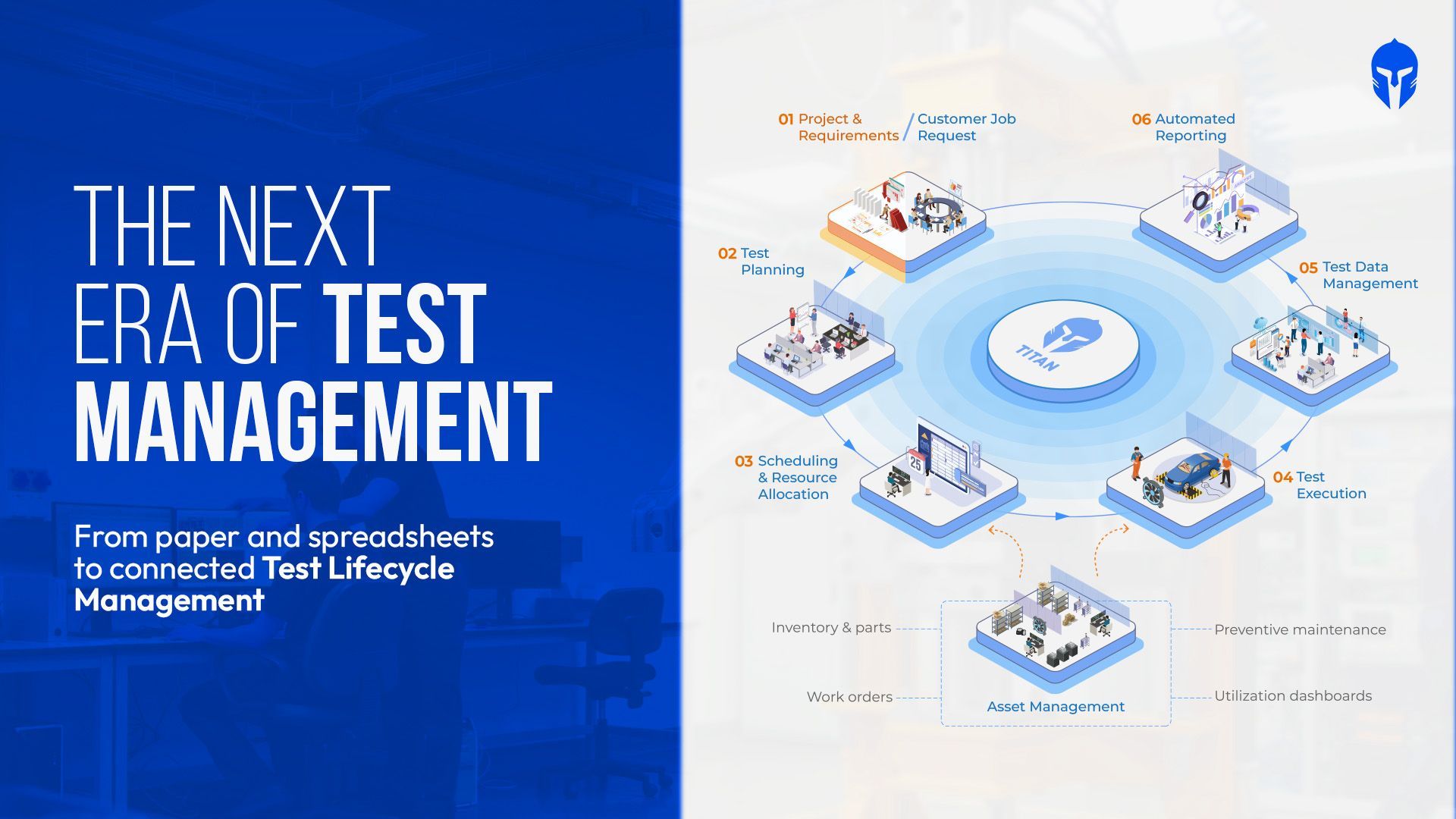
The Evolution of Test Management Tools
Type "test management tools" into a search bar and you get 2 unrelated answers. One set of results covers Jira integrations
Read more...
How to Maintain ISO 17025 Accreditation in Aerospace Testing Labs
It starts with a simple audit question: “Can you show me the calibration record for the equipment used in that test?”
Read more...
Most DVP&R Processes Collapse Before the First Test Even Runs. Here's Why
At some point, the DVP spreadsheet becomes a source of questions instead of answers. Which test count is current?
Read more...
Battery Test Management: How High-Volume Cell, Module and Pack Labs Stay in Control
Weeks into a battery cycle life test, the details start to accumulate: thousands of charge-discharge cycles,
Read more...
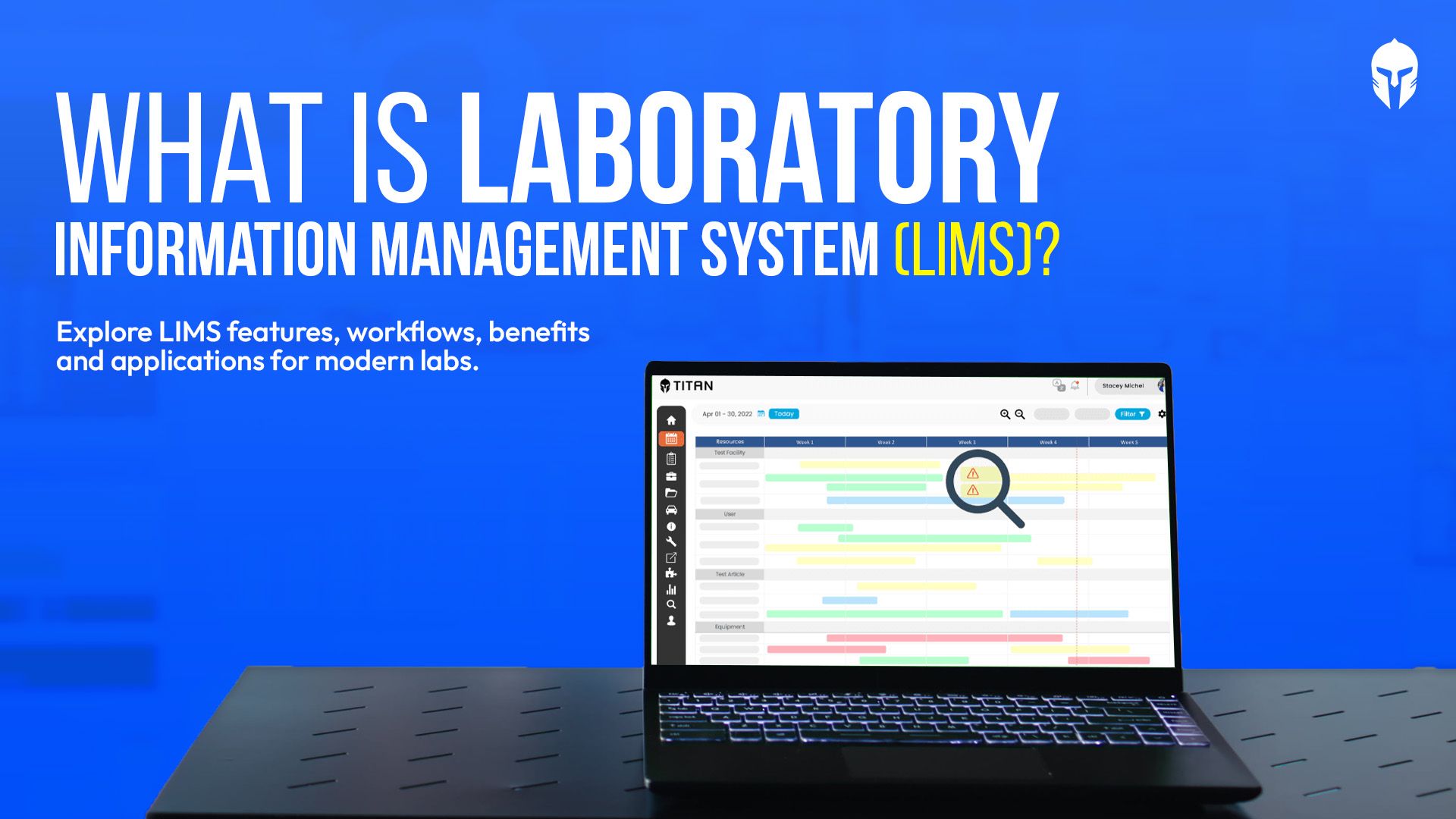
What Is a LIMS? A Complete Guide to Laboratory Information Management Systems
Test requests arrive. Samples or test articles need to be identified. Equipment has to be available and calibrated.
Read more...
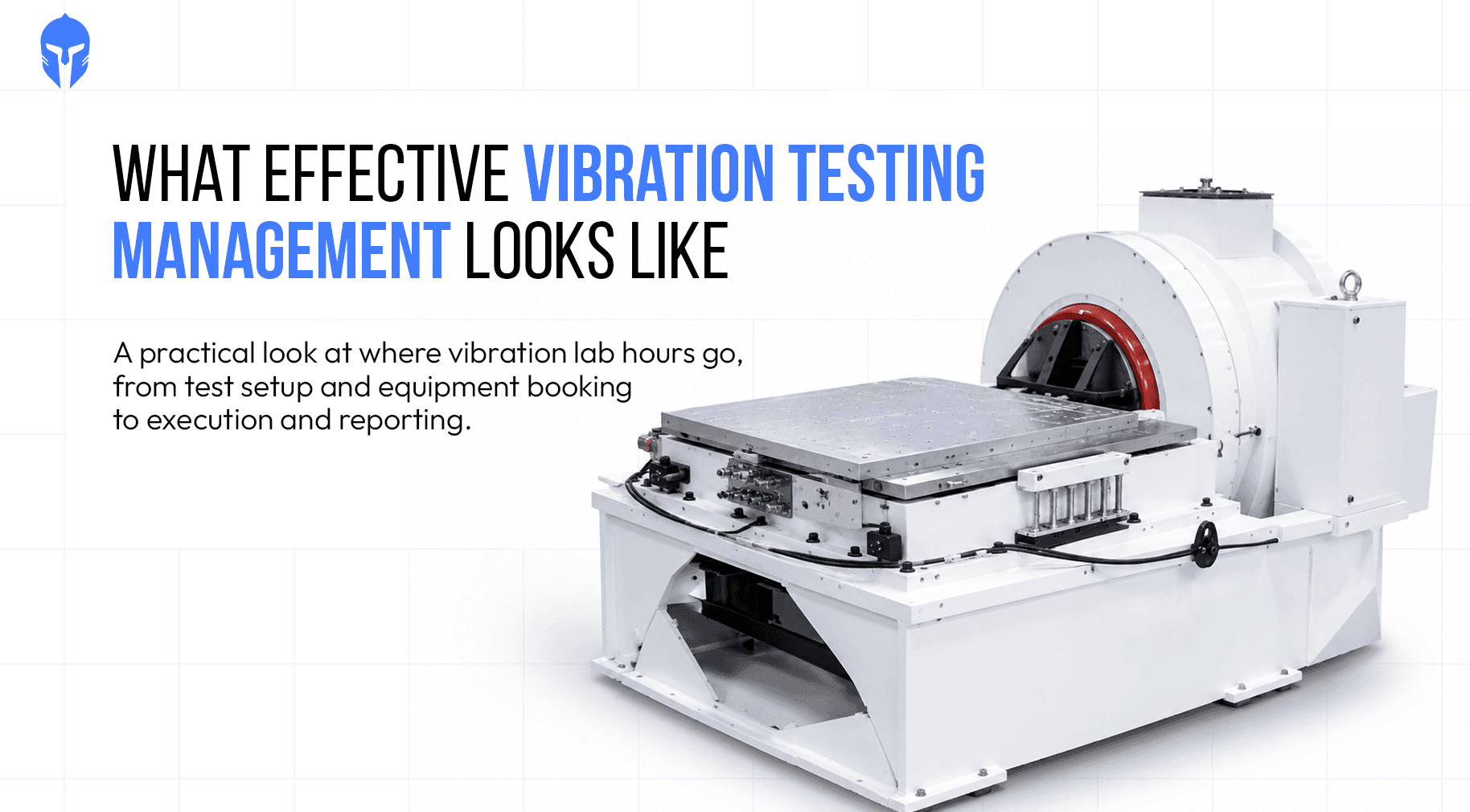
Vibration Testing Management: From Shaker Scheduling to Test Reports
Every vibration test bay runs on a simple ledger. Hours available on the shaker minus hours testing equals hours lost and eac
Read more...

Euro NCAP 2026: Inside the Operational Challenge for Test Labs
Euro NCAP 2026 puts a different kind of pressure on the test lab calendar. More safety functions need to be validated across more scenarios, with the right vehicles,
Read more...

UAV Testing : Following the Traceability Chain of a Single Aircraft
Somewhere in a UAV qualification programme, a seemingly simple traceability question can become unexpectedly expensive.
Read more...
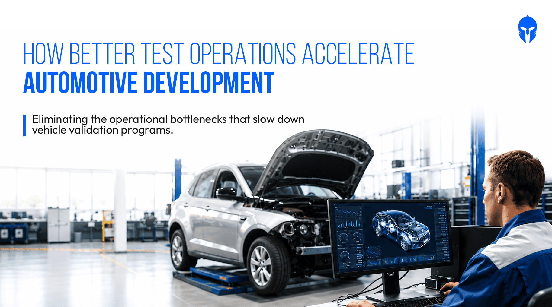
Faster Automotive Development Starts with Better Test Operations
Modern vehicle programs generate an enormous volume of validation activities, test data, schedules and engineering decisions.
Read more...
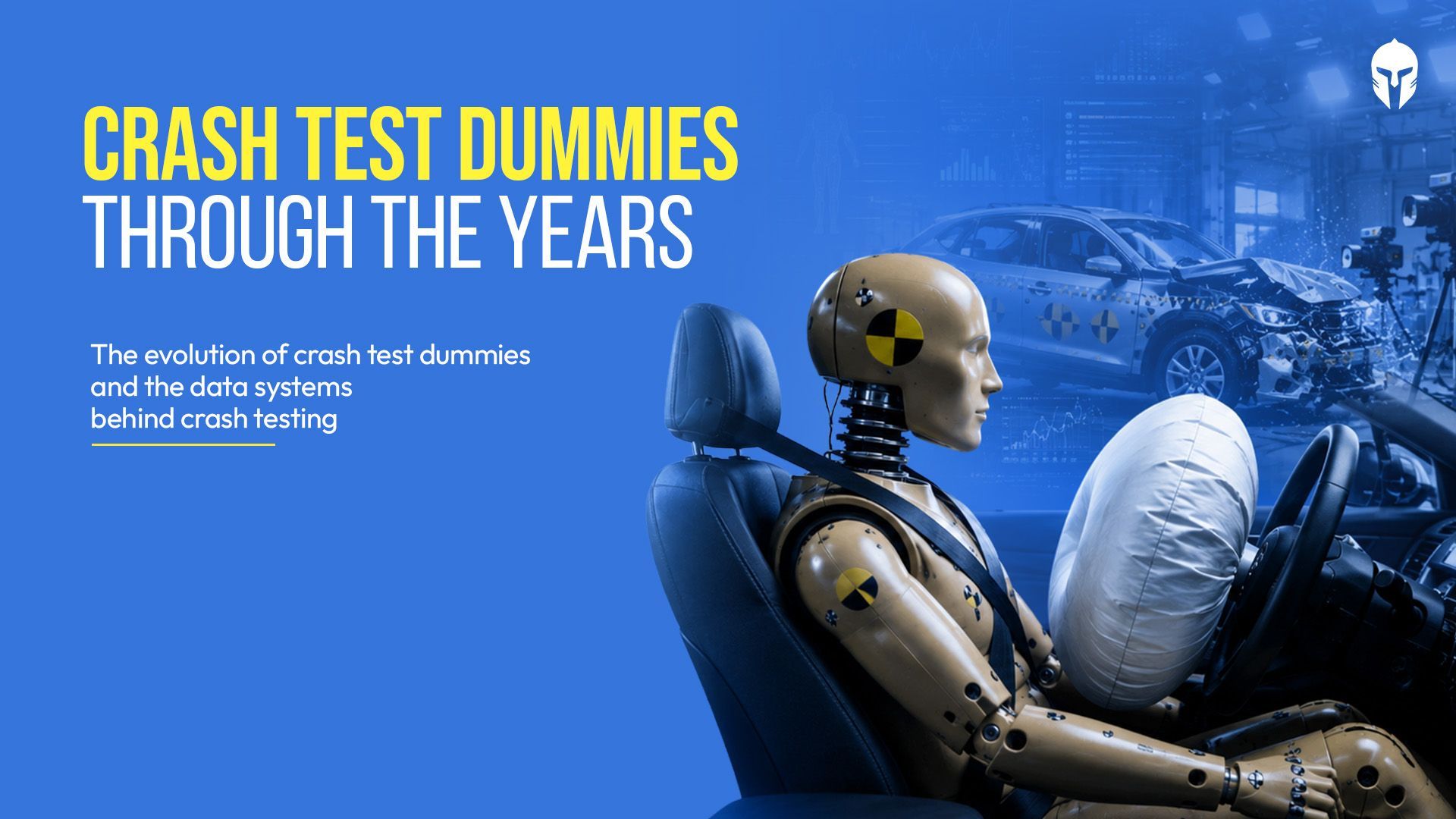
How Crash Test Dummies Changed Automotive Safety
In the late 1940s an Air Force flight surgeon named John Stapp noticed a grim pattern. More of his pilots were dying in cars than in planes.
Read more...
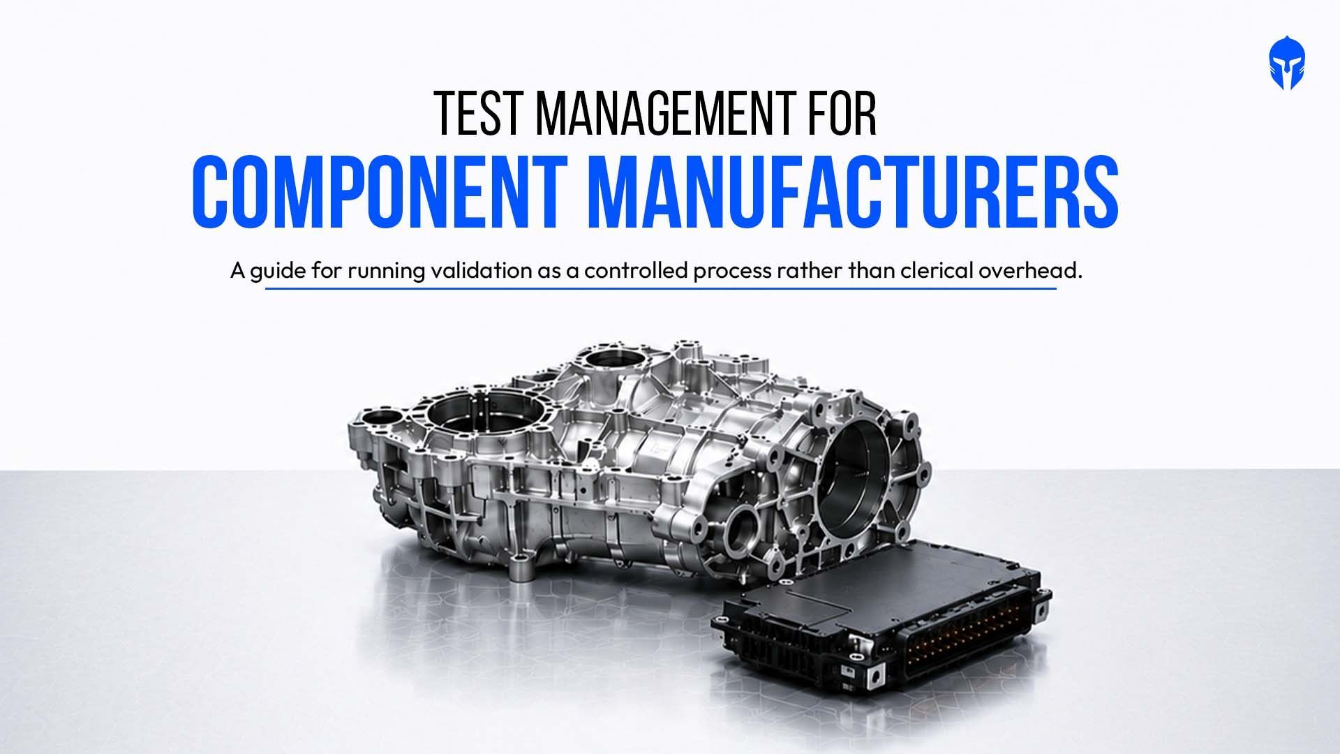
Test Management for Component Manufacturers: How to Run Multi-Customer Validation Without Losing Control
Your lab validates parts for more than one customer. Each OEM arrives with its own requirements, its own report format
Read more...

Stop Testing in Isolation: 4 Surprising Lessons from the Ground
Walk into almost any physical test lab and you will find smart people doing careful work inside their own four walls.
Read more...
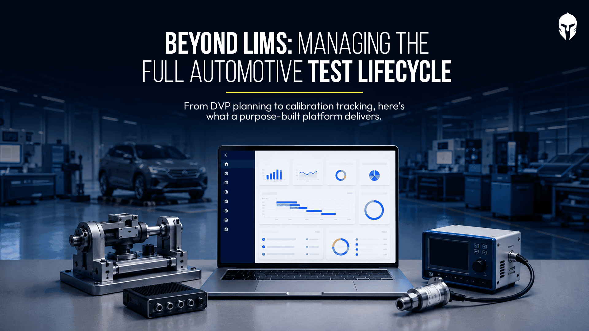
Why Automotive Testing Labs Need More Than LIMS
When engineers at an automotive testing lab search for software to manage their operations, they often land on LIMS.
Read more...
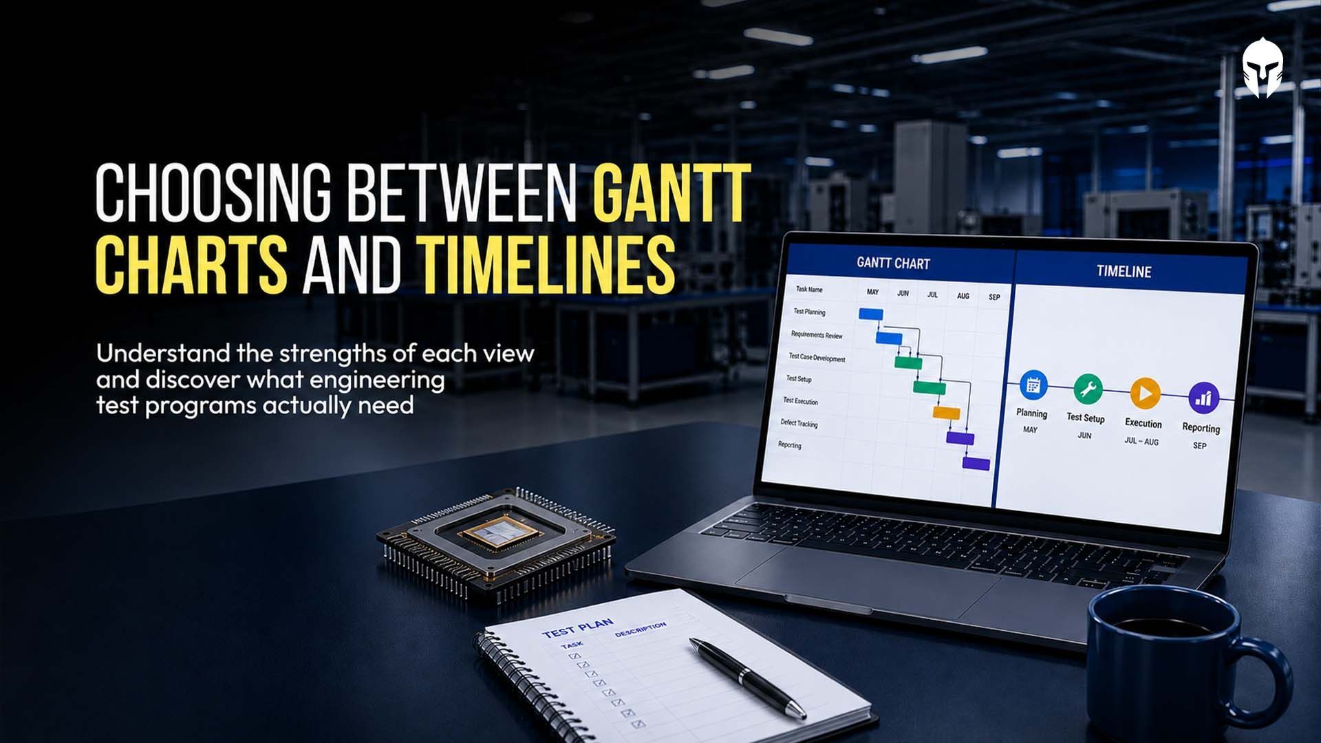
Gantt Chart or Timeline? Picking the Right View for Test Project Management
You open your scheduling tool on a Monday and the program looks healthy. Every test sits inside a neat colored bar
Read more...
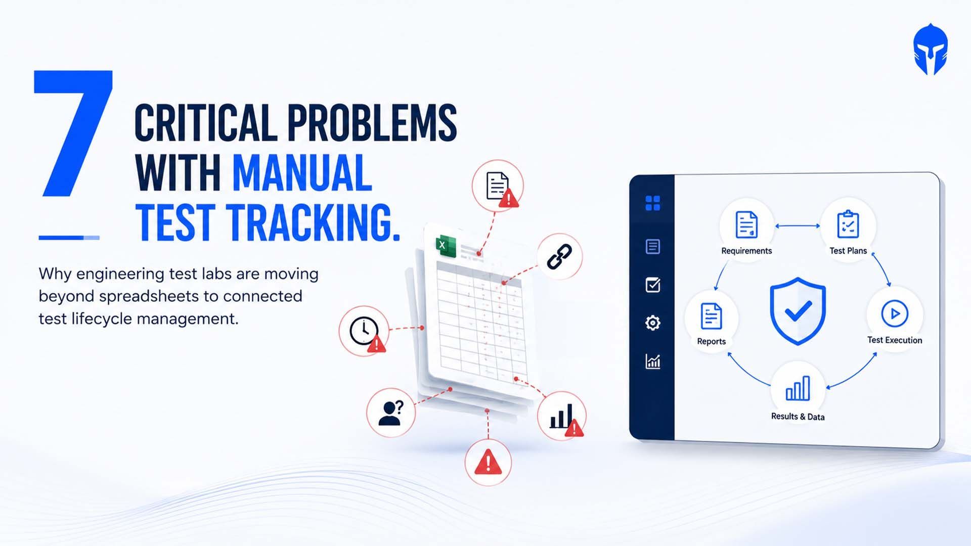
7 Critical Problems with Manual Test Tracking in Engineering test labs
Despite advances in engineering software, many product validation teams still rely on spreadsheets, shared drives and email
Read more...
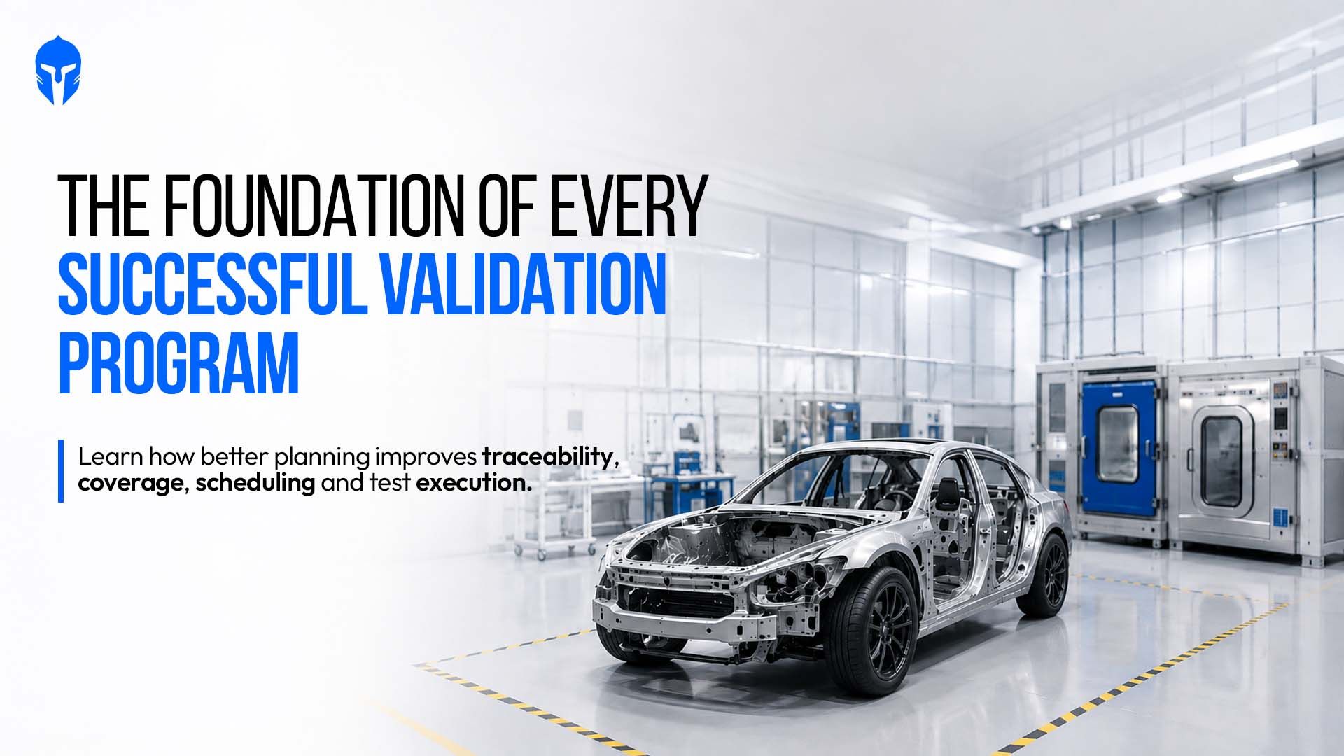
Test Planning Best Practices: How TITAN Simplifies Test Plans, Milestones and Coverage
Ask a validation lead in any physical product test lab how their test plan started and you will hear about a spreadsheet.
Read more...
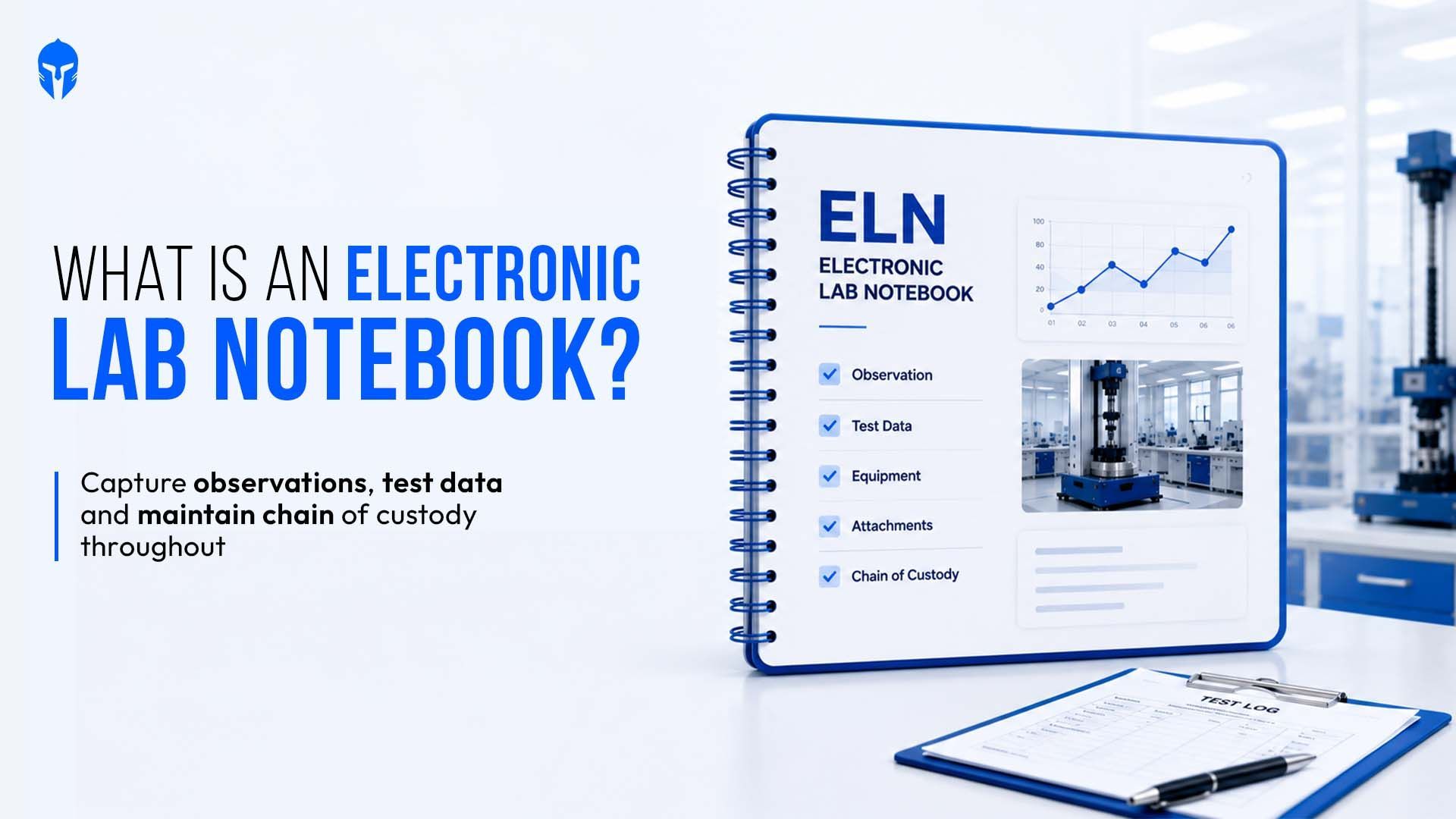
What Are Electronic Lab Notebooks? A Test Lab View
An electronic lab notebook (ELN) replaces the paper notebook used to record experiments, tests, and observations.
Read more...
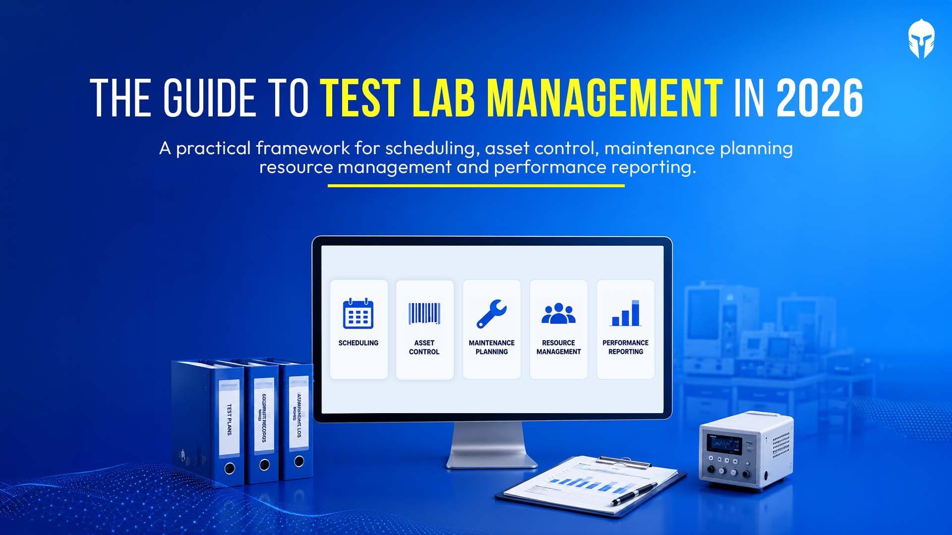
The Complete Guide to Test Lab Management in 2026
Test labs have become one of the most constrained resources in modern product development. Validation timelines are shrinking
Read more...
A Test Planner's Guide to Hardware Validation
Hardware testing sits at the center of every reliable product program. For test planners, the work goes well past
Read more...
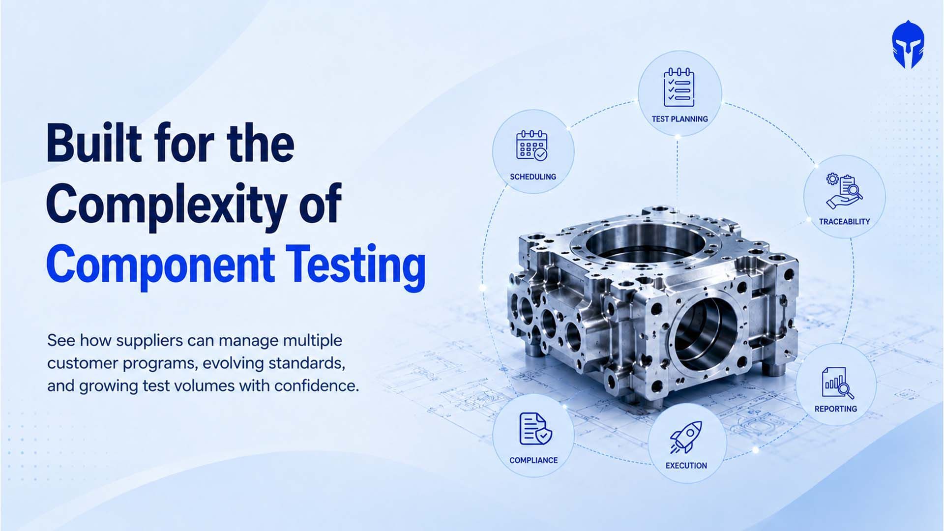
Why Component Suppliers Are Rethinking Test Lifecycle Management
The global automotive material and component testing market reached roughly US$26.91 billion in 2025 and is on track
Read more...
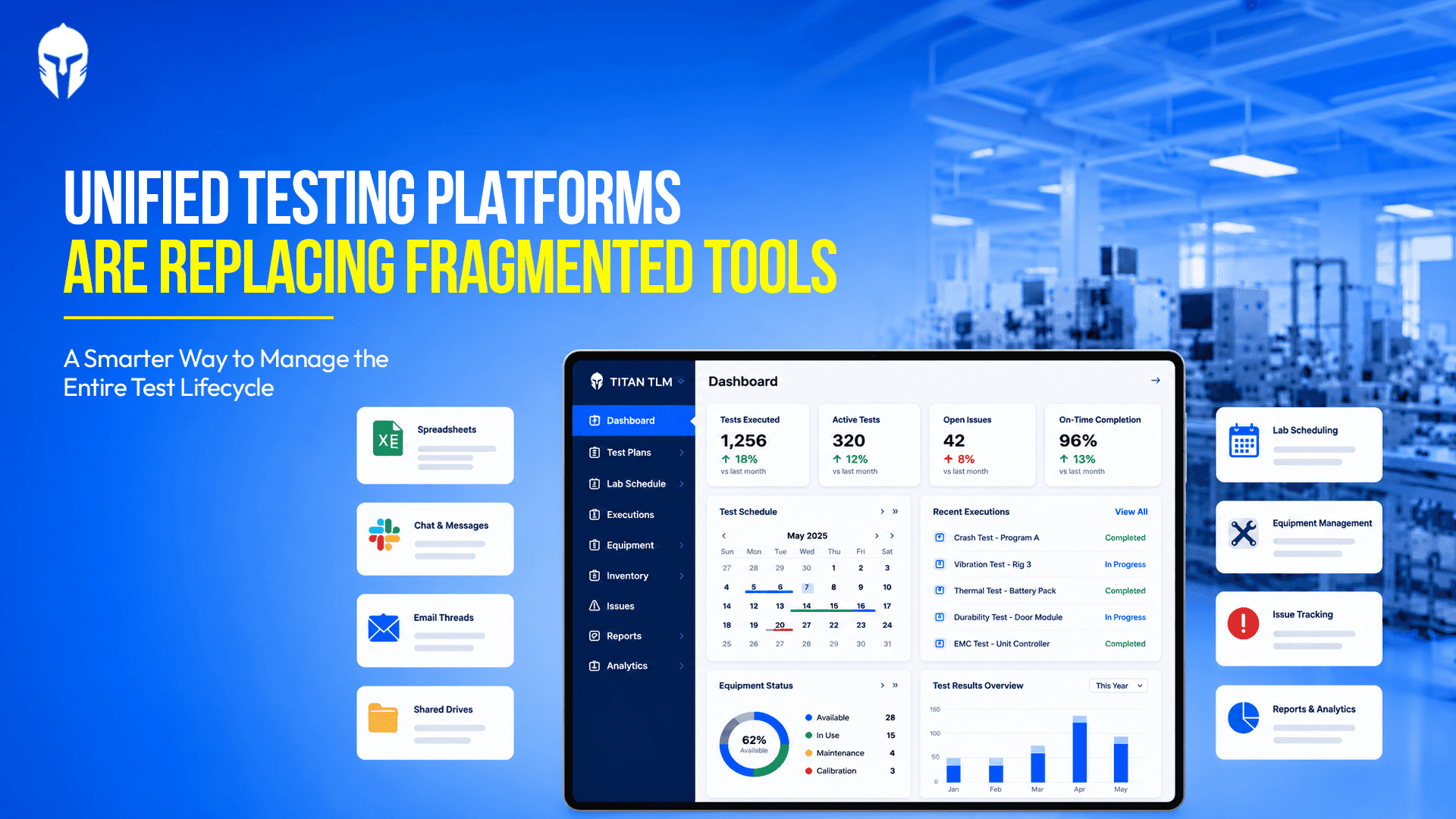
Advantages of using a Unified Testing Platform Over Fragmented Testing Tools
Ask anyone who runs a physical test lab what their week looks like and you will hear a familiar story. The test plan lands
Read more...
The Next 5 Years of Physical Product Testing: A Prediction from the Industry Floor
A product engineer at a mid-size EV components manufacturer spent 14 weeks getting a battery module through
Read more...

How TIC Labs Can Manage Growing Test Volumes Without Losing Operational Control
The Europe Testing, Inspection and Certification (TIC) market is on a sustained growth path. Valued at USD 58.93 billion in 2025
Read more...

The Ultimate Guide to Automotive Crash Testing
Every vehicle on the road today carries the invisible fingerprint of crash testing. Before a single unit reaches a customer,
Read more...

How Leading Chassis and Powertrain Teams Are Closing the Test Traceability Gap
The launch of a dedicated chassis and powertrain testing focus at Vehicle Tech Week North America 2026
Read more...

Premium Wake Boats and the New Rules of Marine Product Testing
Premium watersports boats have become among the most mechanically complex products in recreational manufacturing.
Read more...

What Euro NCAP's 2026 Truck Safety Results Mean for Commercial Vehicle Test Programs
Euro NCAP's 2026 truck safety assessment delivered a landmark result: five out of seven vehicles in the Regional Distribution category
Read more...
A Practical Guide to Choosing and Implementing a Laboratory Information Management System (LIMS)
If you're still running your lab on a combination of spreadsheets, handwritten logs and shared folders with names
Read more...

What -30°C teaches you about a tire
In northern Finland, engineers listen to rubber meet ice in silence so complete it feels deliberate. What they're really chasing consistent
Read more...
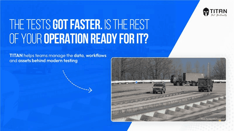
When Robots Take the Wheel: What the Bundeswehr's Driverless Testing Shift Means for Modern Test Operations
Germany's Bundeswehr operates the Technical Centre for Land-Based Vehicle Systems (WTD 41) in Trier, a facility whose sole mandate is to ensure
Read more...
5 Questions Every VP of Engineering Should Ask About Their Test Operations
There's a particular kind of silence that falls over a lab when something goes wrong late in the testing cycle. Not the silence of focus or concentration. A heavier kind. The kind that settles
Read more...
Test Data Management: Best Practices for High-Volume Labs
In a high-volume R&D lab, data is everywhere and that's exactly the alarming problem. Test files, equipment logs, video recordings, structured forms, raw observations
Read more...
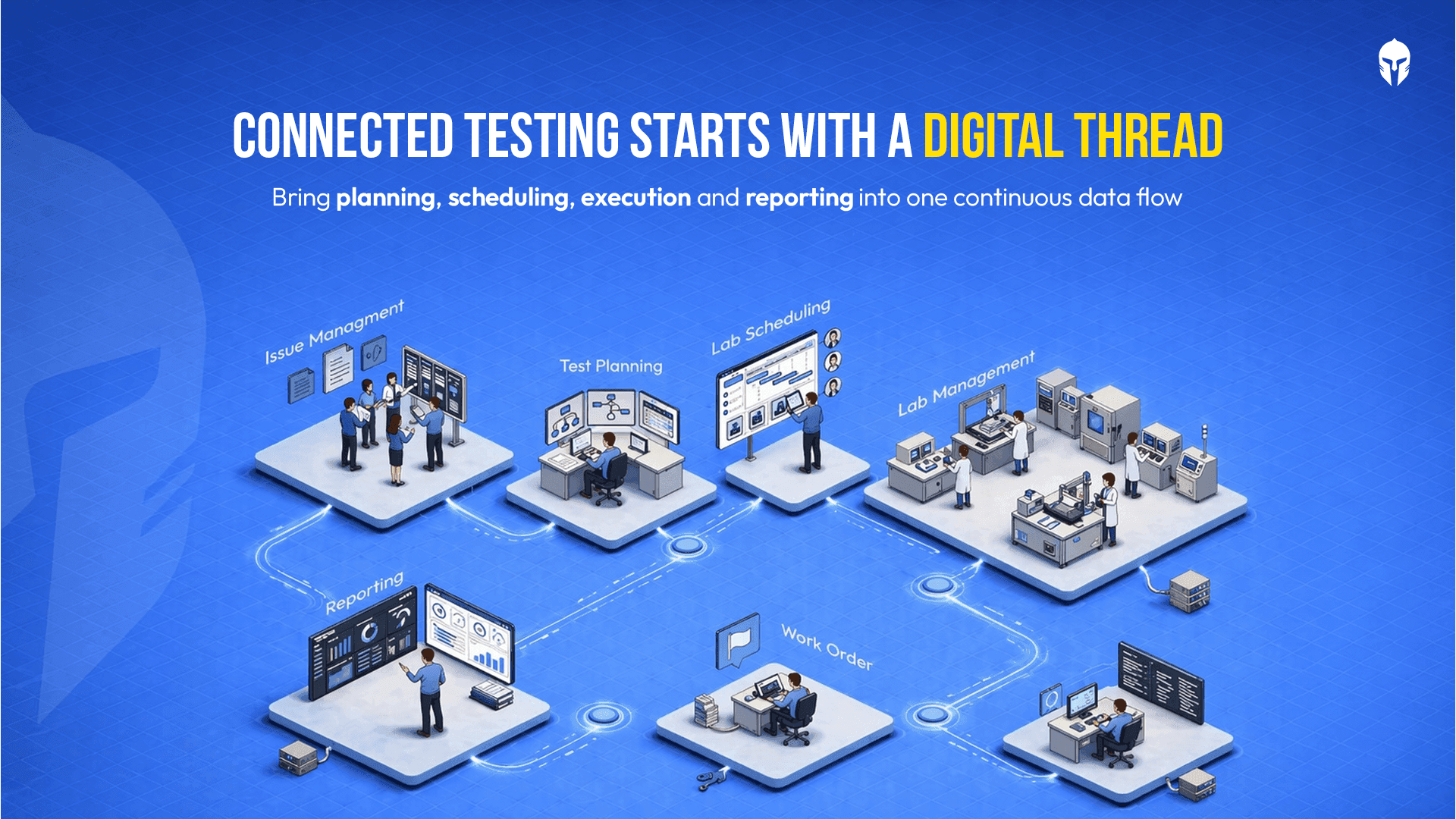
Digital Thread in Physical Product Testing: Hype or Reality?
There is a phrase circulating in engineering circles that sounds almost too good to be true: the digital thread. A single, continuous digital data backbone that connects every phase
Read more...
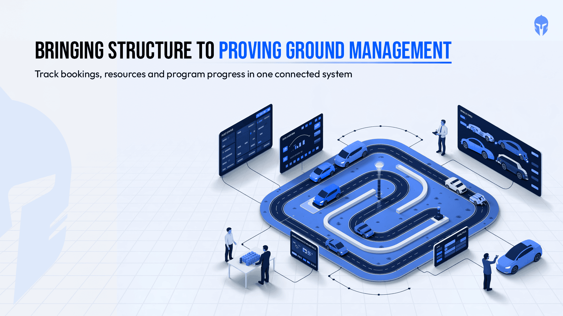
How Proving Grounds Are Going Digital in 2026
Proving grounds have always been the backbone of vehicle validation. Tracks get booked, prototypes get tested, drivers get scheduled and data gets collected.
Read more...

Paper Records vs. LIMS: Choosing the Right Data Management Strategy for Your Lab
For decades, paper-based record keeping was the backbone of laboratory operations. Binders stacked on shelves, handwritten test logs, manually updated calibration sheets;
Read more...
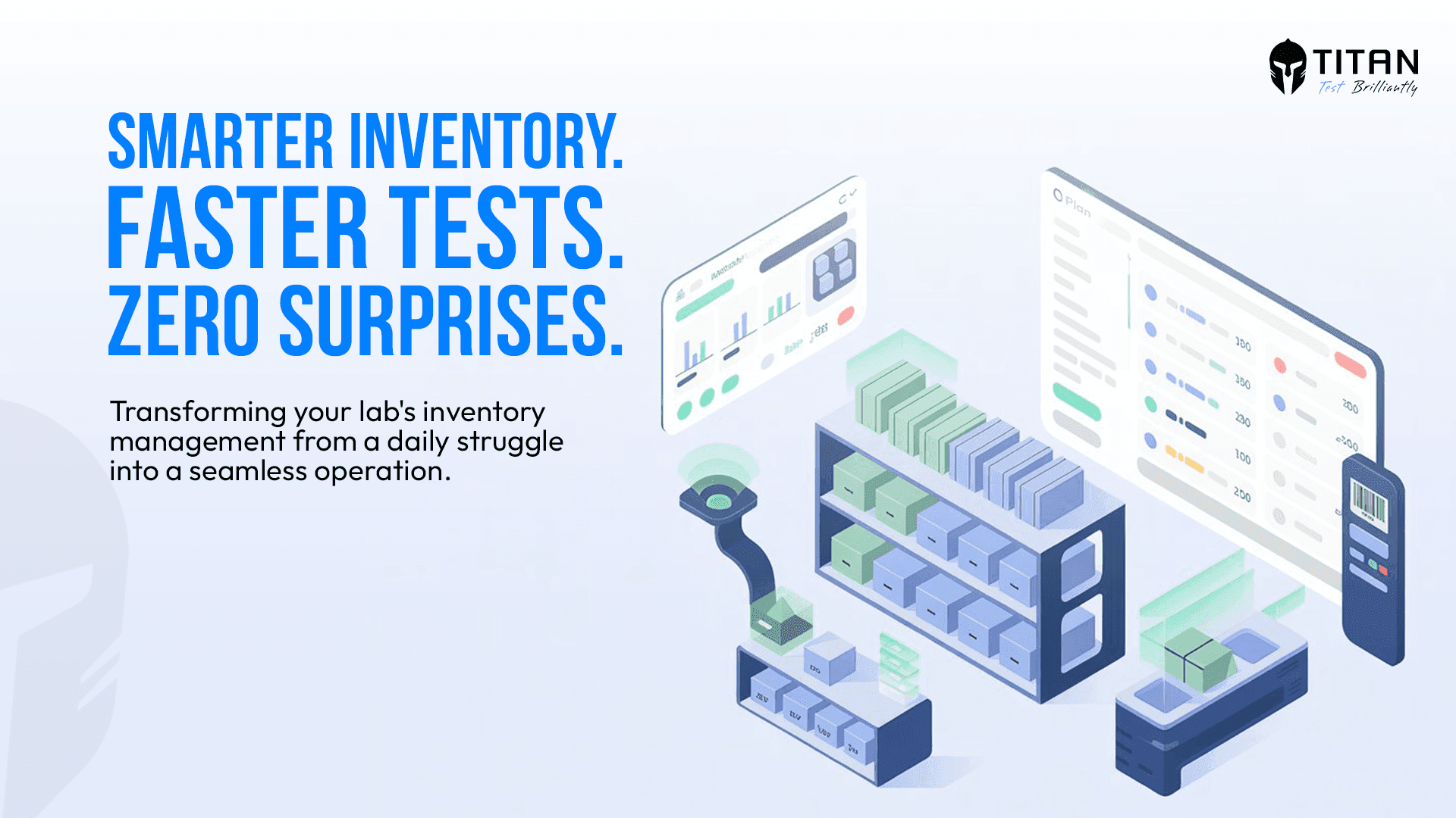
TITAN as The Inventory Management Platform
Running a modern testing or R&D lab without a reliable inventory management system is like navigating without a map. Equipment runs out mid-experiment. Critical spare
Read more...
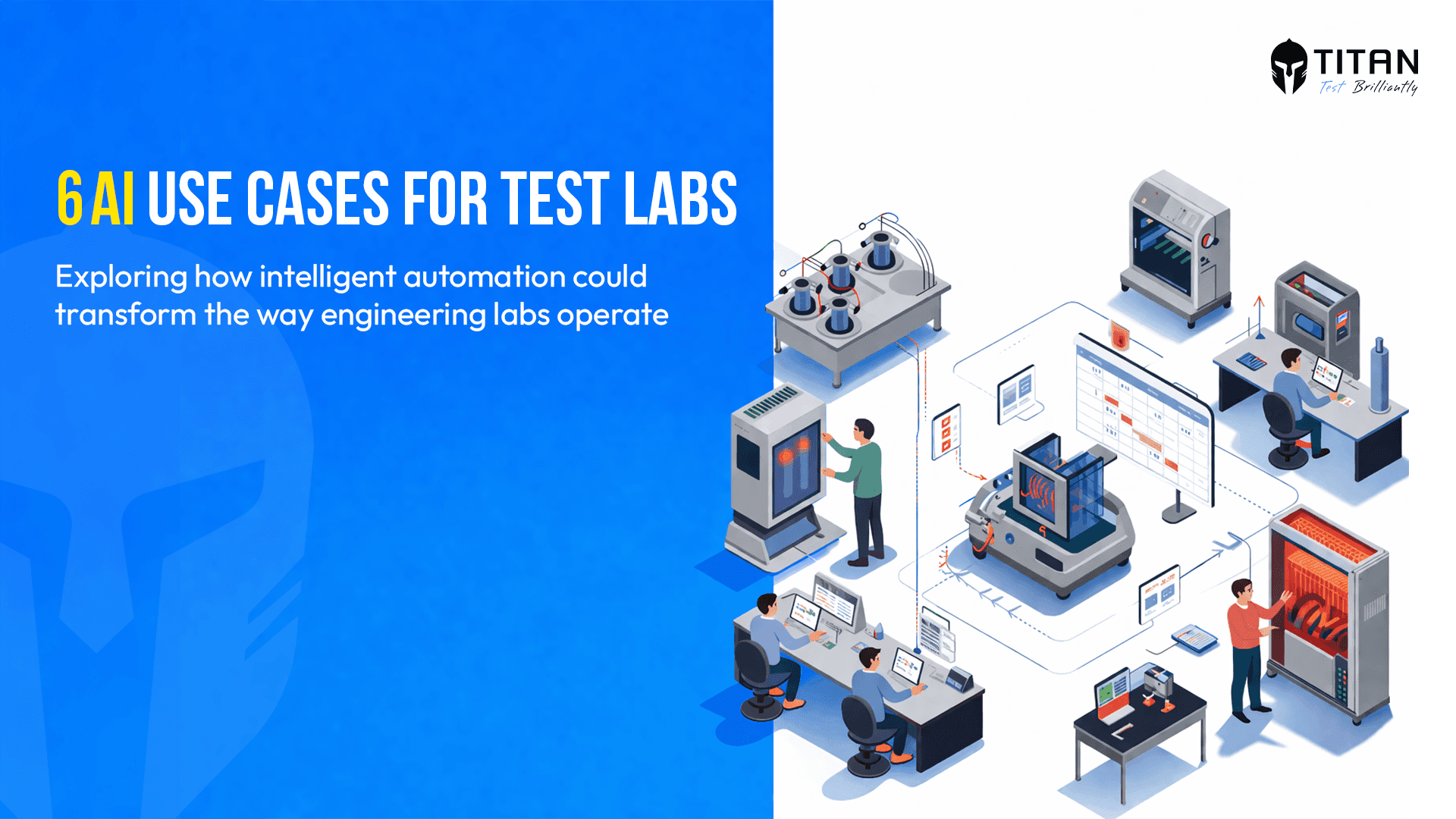
AI in Test Scheduling: Six Use Cases Worth Watching
Test scheduling looks administrative from the outside. Inside an engineering lab, it is one of the most layered coordination problems a team faces and one of the
Read more...

What Every Role in Your Test Lab Needs from One Platform
Running a hardware test lab means managing a constant flow of moving parts, schedules, resources, personnel, data or deadlines. When that flow is smooth,
Read more...

Implementing ALCOA in Your Lab: Gaps, Best Practices and What Good Looks Like
In the previous blog, we covered what the ALCOA principles are and why they apply to engineering and testing laboratories every bit as much as they do to pharmaceutical manufacturing.
Read more...

Why ALCOA Is Not Just a Pharma Principle: What Engineering and Testing Laboratories Need to Know
When most professionals hear the term ALCOA, they think of pharmaceutical manufacturing, clinical trials or FDA-regulated environments. That association is understandable, the ALCOA
Read more...

What Is a Design Verification Plan (DVP)? A Practical Guide for Test Engineers
Design Verification Plans (DVP) sit at the heart of any product development program. They define what gets tested, when, how and to what standard.
Read more...
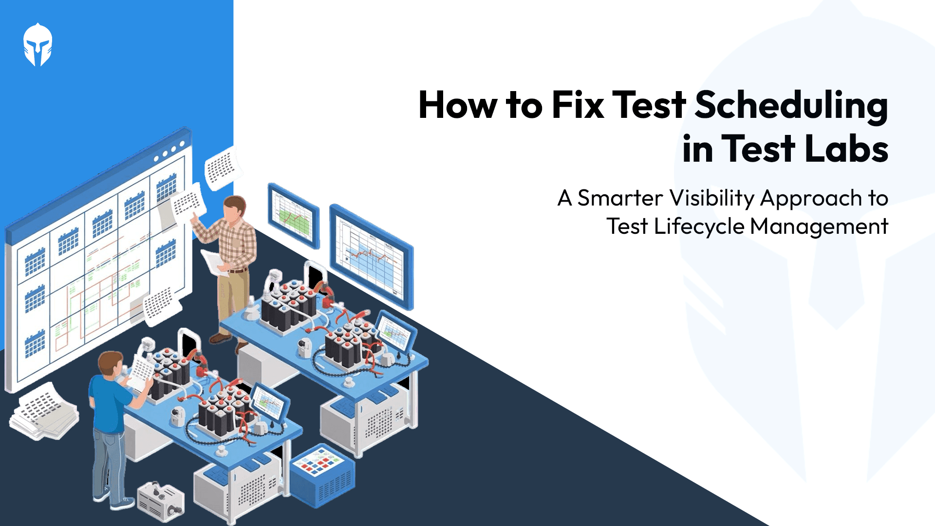
The Test Scheduling Problem Explained
Ask any test engineer what slows down a program and you'll hear the usual answers. Equipment failures. Scope changes. Resource shortages.
Read more...

Home Grown Tools vs TITAN
That internal tool your team built seven years ago. It was genuinely impressive at the time. Someone on the team had a problem; nobody had a budget for a proper solution
Read more...

3 Questions Your Dashboard Should Answer Instantly
There's a framework in operations management that measures any operation across four dimensions - Volume, Variety, Variation and Visibility.
Read more...
How Smart Scheduling Is Beating Million-Dollar Equipment Investments?
You invested heavily in advanced equipment because precision matters. Calibration matters. Speed to market matters. Yet despite those investments,
Read more...
Crash Test Dummies Aren’t Props, They’re Precision Instruments
Step into a contemporary crash testing facility and one thing becomes clear almost immediately.
Read more...
OEM and the Hidden Cost of Fragmentation: Why Test Lifecycle Management Matters?
Picture a weekly sync inside an automotive OEM program, their verification and validation (V&V) teams racking their brains over spreadsheets.
Read more...
How Do You Build ISO/IEC 17025 Ready Labs with End-to-End Digital Traceability?
If you run or work with testing and calibration laboratories whether as an OEM lab, an independent testing facility
Read more...

Any Ambition Bigger Than a Spreadsheet?
Imagine this: It's late on a Friday evening, and Sarah, a dedicated vehicle test engineer at a leading R&D organization,
Read more...
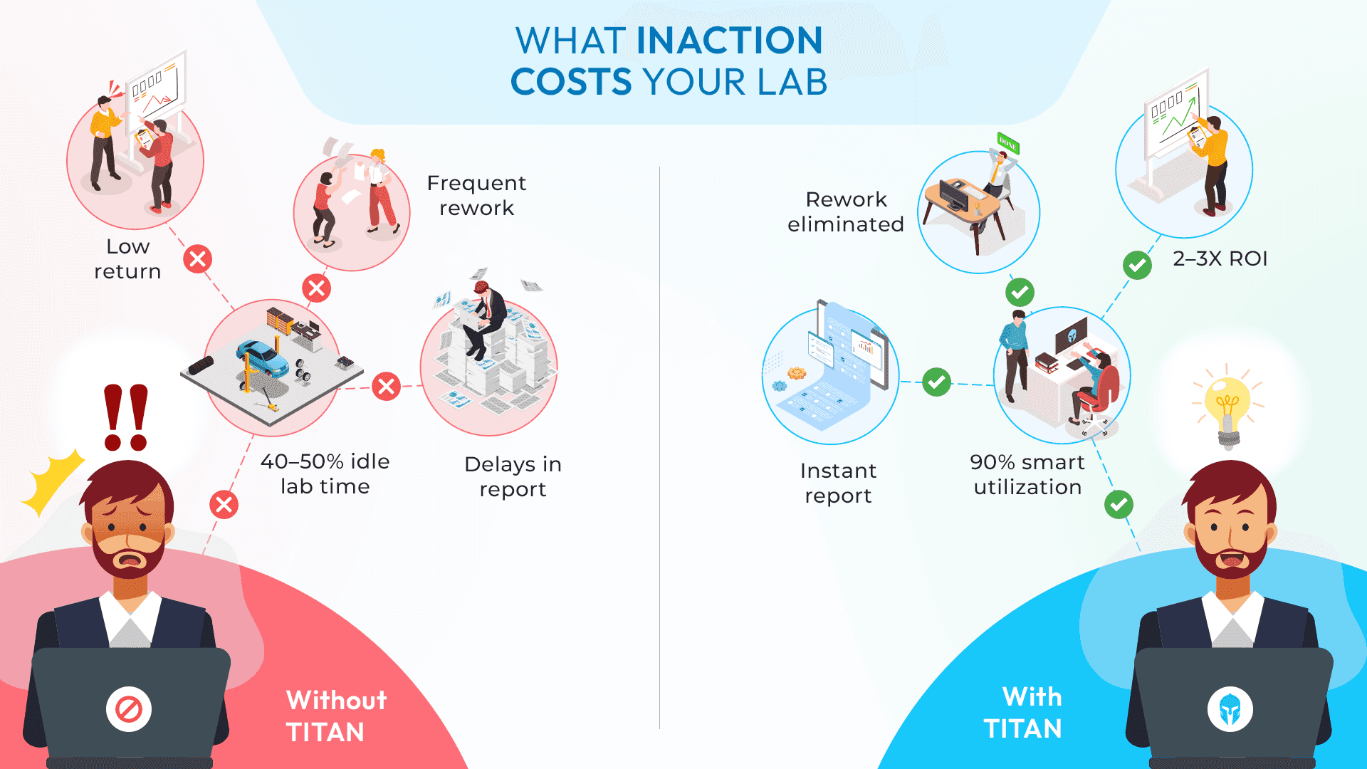
The Cost of Inaction: Why Testing Teams Can't Afford to Delay a Test Lifecycle Management Solution
Many engineering leaders already know their testing teams need a centralized system. The challenge?
Read more...
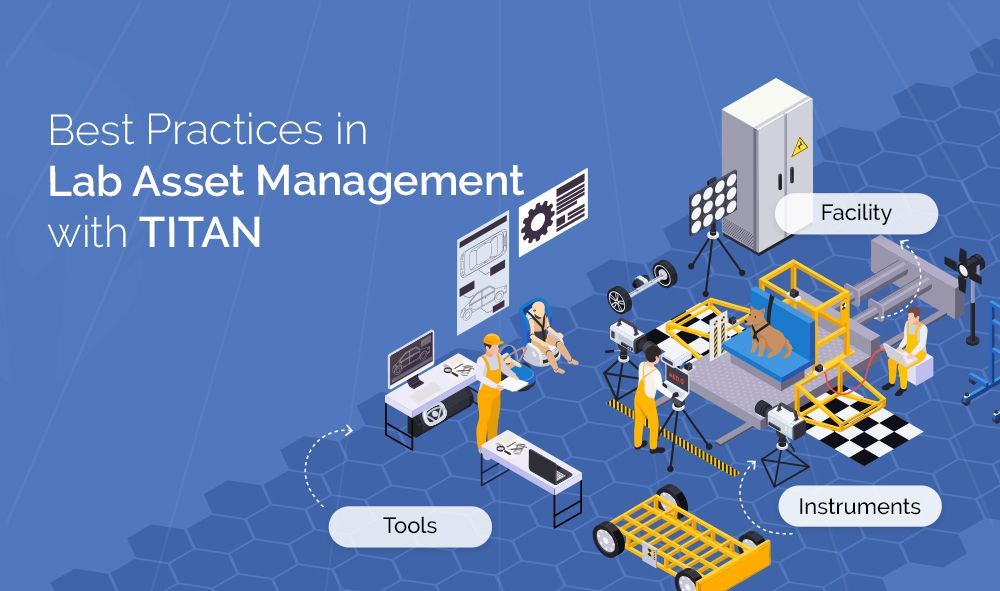
Best Practices in Lab Asset Management with Titan
Modern laboratories operate under constant pressure: deliver accurate results faster, manage rising costs,
Read more...
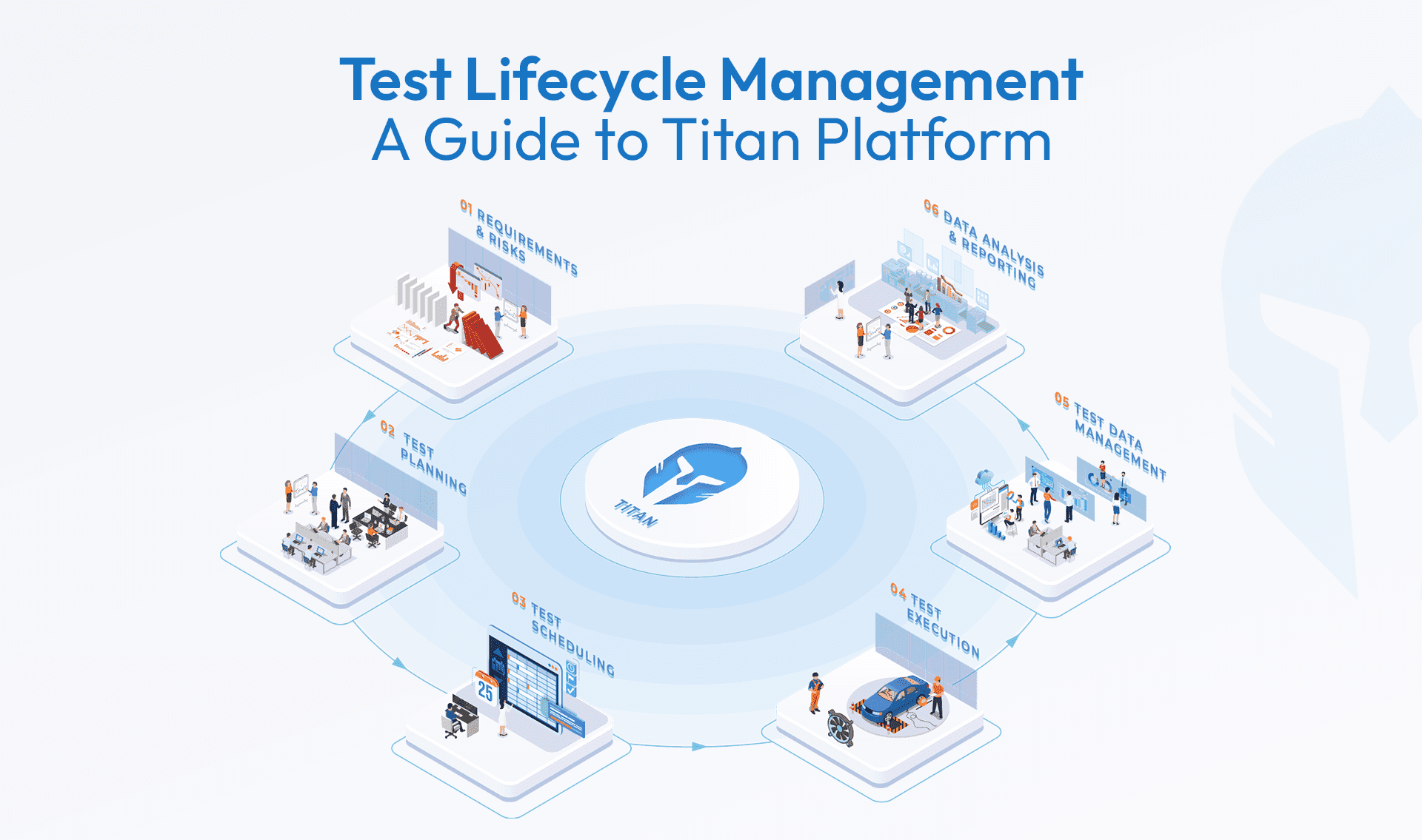
Test Lifecycle Management Explained: What Every Engineering Team Needs to Know
When it comes to product development, testing is more than a box to check it’s the process that validates safety, performance,
Read more...
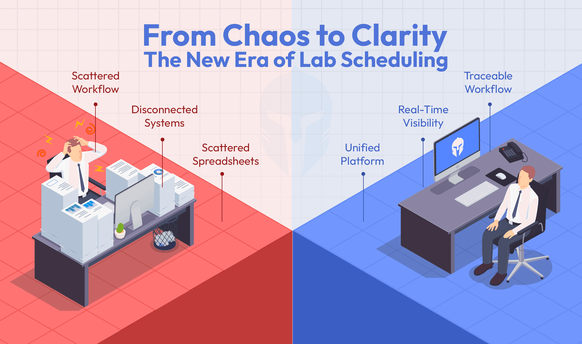
Can your booking tool do more than just schedule?
Titan's Booking Portal does more than just schedule. It’s a single platform that links test requests,
Read more...
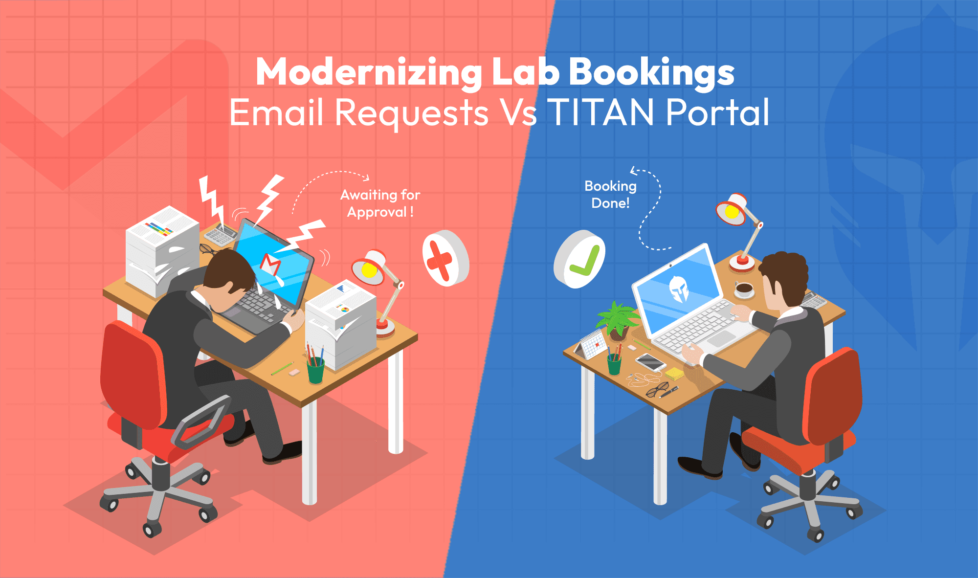
Modernizing Lab Bookings: Email Requests vs. Titan Portal
When managing test labs or proving grounds, it’s common to rely on email threads and manually filled forms from customers
Read more...
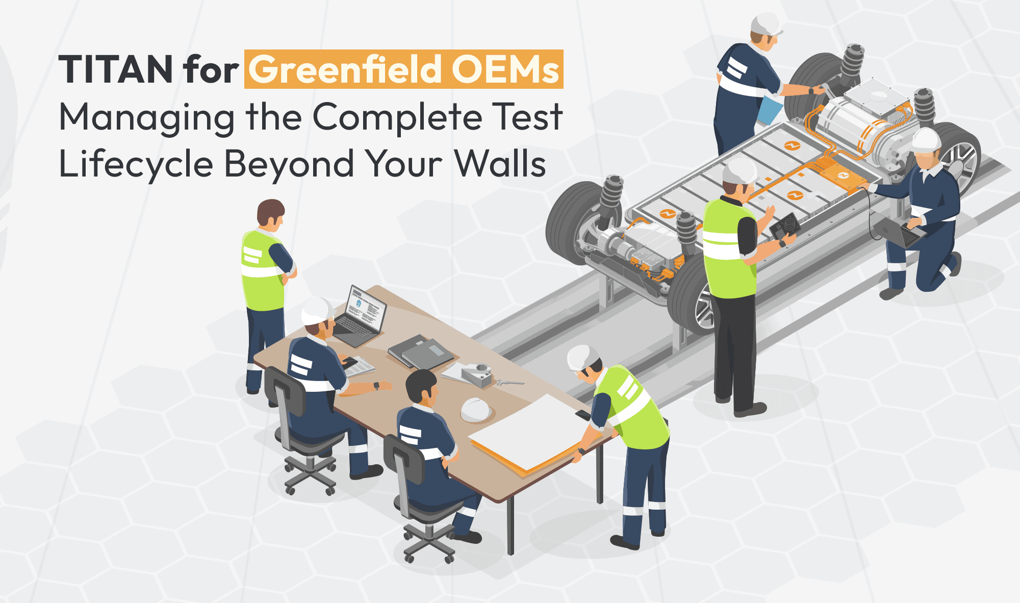
Titan for Greenfield OEMs: Managing the Complete Test Lifecycle Beyond Your Walls
Building a product from the ground up as a Greenfield OEM comes with unique challenges.
Read more...
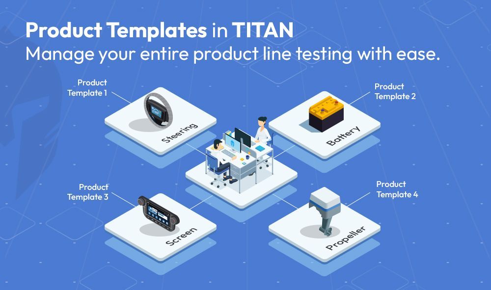
How Titan’s Template-Driven Approach Simplifies Multi-Product Line Test Management
Engineering teams managing diverse product lines often face the challenge of maintaining consistency,
Read more...
How TITAN Supports Laboratories in Achieving ISO/IEC 17025 Compliance
Laboratories across industries are tasked with ensuring the highest standards of testing and calibration.
Read more...

Managing Test Articles Seamlessly with Titan - from Creation to Retirement
In the world of product testing, managing prototype samples and test articles is often a logistical challenge.
Read more...
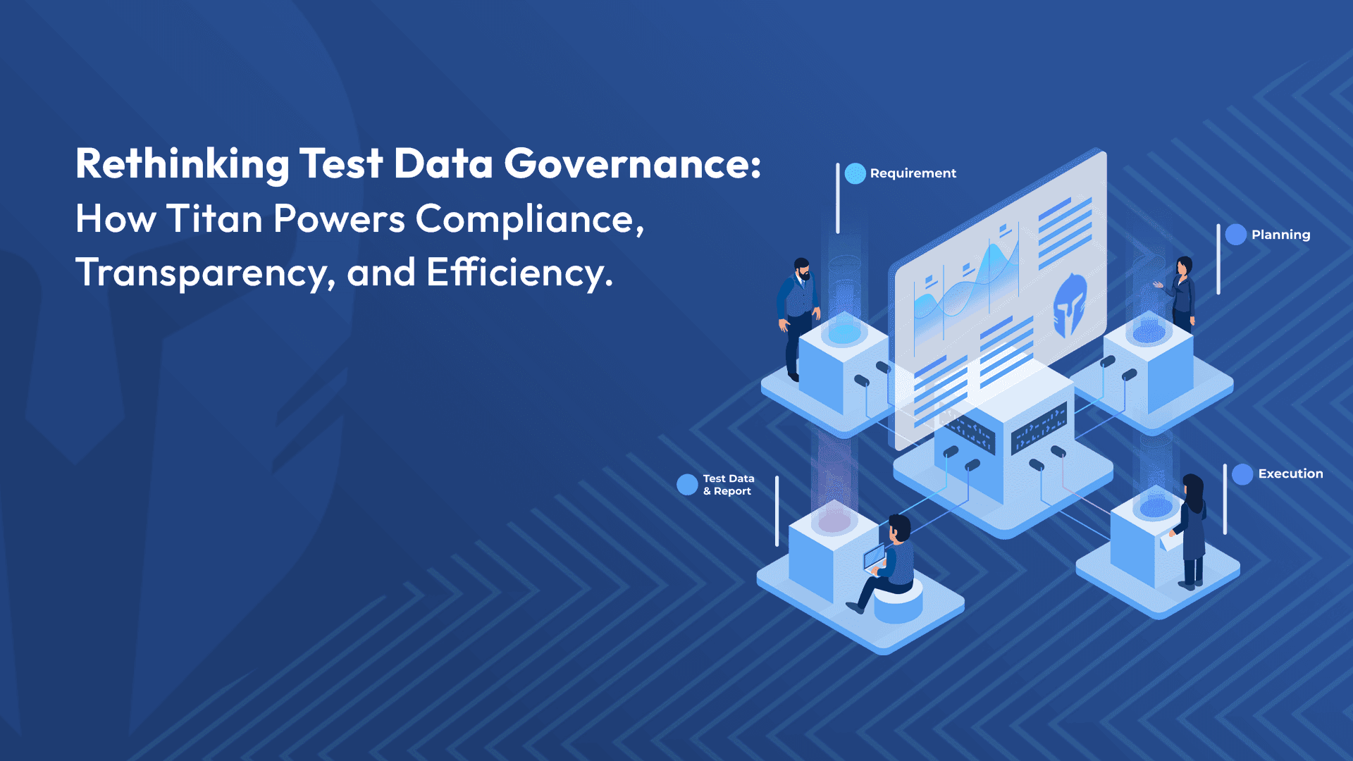
Rethinking Test Data Governance: How TITAN Powers Compliance, Transparency, and Efficiency
In today’s data-driven testing environment, governance leaders face increasing pressure to ensure compliance
Read more...

Bridging the Scheduling Gap for Modern Test Labs: Why TITAN Is Your Lab's Best Ally
Imagine this: A test lab under constant pressure to meet deadlines is struggling with delays and resource conflicts.
Read more...
From Feedback to Feature: The Addition of Inventory Management in TITAN
Over the years, Titan has evolved by listening closely to the needs and feedback of our customers. As a company that values
Read more...
The Essential Synergy: How a unified Test and Lab Management tool enhances your engineering products’ verification and validation experience?
In the world of engineering product verification and validation (V&V), traceability and efficiency are paramount to giving the earliest green signal for a market launch
Read more...

Streamlining Test Management: Best Practices for Effective Scheduling and Resource Allocation
Efficient management of test requests and scheduling is crucial for any engineering or testing department.
Read more...

Transforming Verification Plan Management with TITAN: Overcoming Traditional Challenges
In today’s fast-paced technological environment, managing verification plans (VPs) with outdated tools like spreadsheets or standalone systems....
Read more...
Streamlining Electronics R&D with TITAN's Advanced Testing Features
In the dynamic world of electronics manufacturing, quality isn’t merely a desirable attribute -- it's critical for achieving market success and maintaining customer trust.
Read more...
Eliminate Productivity Killers with TITAN
Administrative tasks are often the silent killers of productivity, diverting engineering teams from their core mission: driving product improvement,....
Read more...

Maximizing Efficiency in Test Management: The Case for Choosing TITAN Over Custom Solutions
You recognize that streamlining and automating your testing processes will enhance quality while reducing costs. As you consider the idea of creating a....
Read more...
Inventory Management– Never Run Out of Consumable Material Again with TITAN!
In addition to its full end-to-end test management capability, Titan also features a robust Inventory module. Now you can manage all the consumable items that....
Read more...
Preventive Maintenance – Another Great Feature from TITAN!
A testing team understands that it is only as good as its equipment. If equipment is neglected -- or maintained incorrectly -- the organization is at risk,....
Read more...

TITAN: An Engineer’s Ally
Greetings fellow engineers, we're excited to introduce your new ally, dedicated to your work satisfaction. Over the years, we have had meetings and discussions ....
Read more...
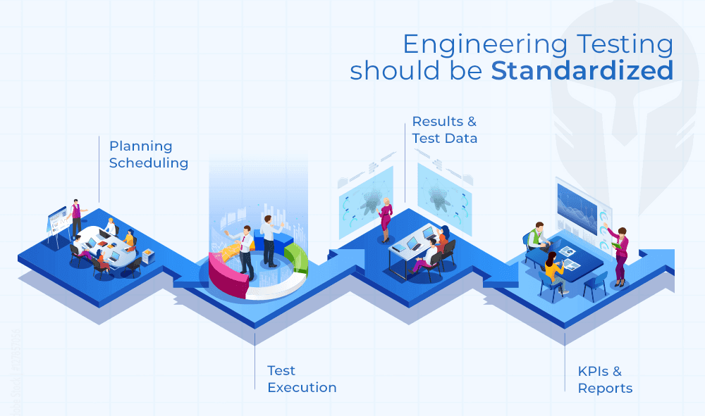
Standardization: Engineering Testing Should Be Standardized, too!
Engineering and IT executives are continually on the hook to deliver savings while streamlining processes and improving quality....
Read more...
Meeting the Crash Testing Challenge
You get one chance to get a crash test right. There are no do overs. You need to ensure every step has been followed meticulously, checked and double checked....
Read more...
DVP Essentials: How TITAN Guarantees Comprehensive Test Coverage with Enhanced Product Quality
In today's fast-paced manufacturing landscape, product success relies on robust design and validation processes. Rushing products to market can lead to....
Read more...
Standardization of Testing Practices – How TITAN Makes It Happen!
Enforcing corporate-wide standardization is a challenge. Over the course of doing business, each engineering department has developed specific testing processes....
Read more...

How TITAN provides Flexibility and Configuration Options for your Unique Workflows ?
When it comes to testing, every organization has its own distinct processes, workflows, and requirements. One-size-fits-all solutions often fall short of....
Read more...
I love making reports. Said NO ENGINEER. EVER.
Every engineer procrastinates preparing a test report as the efforts are high and it consumes lot of his engineering hours. Having said that, test reports remain critical....
Read more...

Challenges in Autonomous Vehicle Testing and Validation
A study, prepared by Strategy Analytics, predicts autonomous vehicles will create a massive economic opportunity that will scale from $800 billion in 2035....
Read more...
Test Report Generation Challenges In Automotive Industry
Ever wondered how the wheels of vehicle development keep turning smoothly? In the fast-paced realm of vehicle development, where informed decisions....
Read more...

Need For Prototype Vehicle Management System
Prototype testing has been around for as long as humans have been inventing. Creating the best version of a tool requires trial and error, and without testing,...
Read more...
A Complete Guide: Crash Testing For Automobile
A Complete Guide: Crash Testing For Automobile Road accidents are the major cause of death worldwide, even after strict rules and heavy...
Read more...
How To Manage End-To-End Vehicle Test Process
How To Manage End-To-End Vehicle Test Process Testing Beyond Boundaries With TITAN TITAN has established itself as a leader in vehicle...
Read more...
Test Incident & Concerns Management
Test Incident & Concerns Management In developing any new product, you invest a great deal of time and energy into testing your products...
Read more...
Why do you need Test Lifecycle Management
Why do you need Test Lifecycle Management We’re living in a time period where we have integrated software tools and apps into every...
Read more...